Disclosure: This DIY simply describes the process I used in order to do my own installation but I take no responsibility for your car. You are performing this install at your own risk and I cannot be held liable for any damage to your car. Anyone considering this install should most certainly copy of their DME pinout diagram. The wire references below are specific to the Z4 3.0si (n52 engine) with MSV70 ecu.
Installation
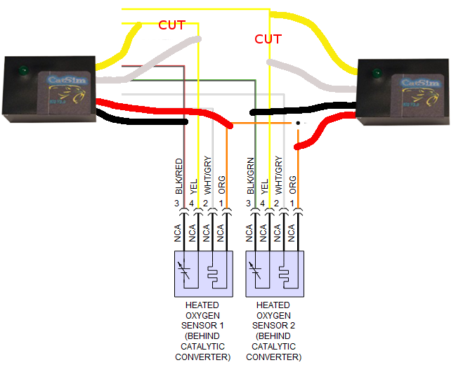
The o2 simulator has 4 wires that connects to 3 wires from your cars. From your car, you can access these wires whether from the o2 sensor (or harness) or the DME. Using the o2 sensor / harness is less “risky” but may not be a viable option depending on your engine layout. Accessing from DME comes with risk is you choose wrong wire but has benefits of being closed/hidden.
1. Take note of general mapping for wires (o2 simulator -> car)
- red wire from the o2 sim ->12v (power)
- black wire from the o2 sim -> rear o2 ground
- yellow and gray wires from o2 sim -> rear o2 signal
2. Connect the red and black wires first just so you can verify the unit is powering up (green light will flash).
3. Next step is to connect the yellow and gray wires from the o2 sim. One end will connect to your gray o2 sim wire and the other end will connect to your yellow o2 sim wire. This makes sense as the signal from your o2 sensor needs to be processed by the simulator before reaching your DME.
Note you do NOT need to cut the 12v or ground wires but you WILL need to clip the rear o2 signal wire. Before making any cuts however, be sure there's enough length for you to connect each end of the signal wire to your sim.
3A. If installing the o2 sim onto the rear o2 sensor (or harness), A74 was kind enough to send me this diagram:
3B. If installing the o2 sim by the DME (which is what I did), I tapped the following wires for the MSV70:
Sub-connector x60002 (26 pin)
wires 19 & 20 for rear o2 signal
wires 23 & 24 for rear o2 ground
Sub-connector x60003 (6 pin)
wire 1 for 12v (power)
Keep in mind these wire references may differ so more the reason to get the pinout diagram and confirm which wire does what. I’ve attached below the pinout diagram for my 3.0si N52 coupe.
4. After connecting the correct wires, I tucked the sims back inside the DME enclosure, hooked up my laptop, cleared codes and reset adaptations.
Total install time was 30 mins (though I probably read whatever instructions I could gather for an hour to muster up the confidence to tap my DME wires). To be honest, the most difficult part was reinstalling the DME with the birds nest of wires. As to why I chose the DME route, installing by the o2 connector on my N52 wasn't even an option because the harness connects underneath the car unlike the S54/N55 where it sits up top. Secondly, as mentioned above, by installing it in the DME enclosure it's totally out of sight and will be protected from heat/cold/wet. The only downside of course is that cutting/tapping any wire leading to your DME is cringeworthy...