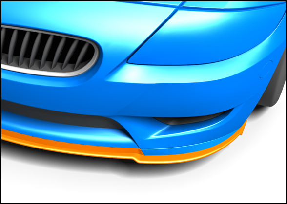
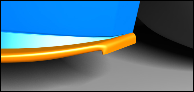
I knocked up a simple first draft splitter. Rather than being flat it consists of inverted aerofoil sections to increase the overall downforce versus a flat counterpart. I have added a small endplate detail on the extremity to house the vortex better at lower front ride heights.

The front end of the car is relatively bluff and therefore air is forced up, down and sideways from the stagnation point. In the picture below it can be observed from the centreline streamlines that there is a strong downwards trajectory of the flow directly in front and above the splitter. Note that everything else in the image is coloured by pressure (red high, blue low)
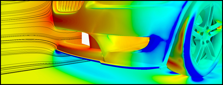
By having the aerofoil sections this flow is turned over 90 degrees and gives rise to a local acceleration and therefore pressure drop whilst maintaining fully attached. On conventional splitters with a very small radius it is not uncommon to have a separation bubble near the leading edge. It can be seen below that the whole splitter or front diffuser is yielding a pressure drop and contributing to generating downforce.
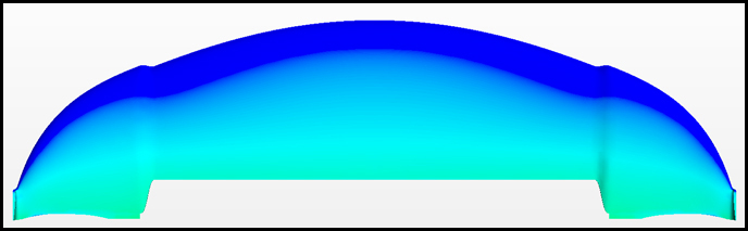
This simple front diffuser is already yielding in the order of 9 kg of added downforce at 180 km/h. I have got several ideas to push this further and improve the aesthetics, making it more integrated and flowing with the lines of the car!
