

| BMW Garage | BMW Meets | Register | Today's Posts | Search |
|
|
|
 SUPPORT ZPOST BY DOING YOUR TIRERACK SHOPPING FROM THIS BANNER, THANKS! |
|||||||||
Post Reply |
|
|
Thread Tools | Search this Thread |
| 12-16-2010, 10:39 AM | #1 |
|
Enlisted Member
 6
Rep 43
Posts |
Z4 (E85) - DIY for Installation of Hard Top Prep Kit
Z4 (E85) - DIY for Installation of Hard Top Prep Kit
My 2008 E85 Z43.0si Roadster was not delivered from the factory with the $75 hardtop preparation option, thus the installation of a hardtop was not possible for me unless I could retrofit this prep kit into my car. I am aware that most -- if not all -- of the Z4s delivered into the European market are already fitted with this prep kit, but that very few Z4s delivered into the US market are so equipped. In a previous thread, I had inquired as to whether the Hardtop Prep Kit DIY instructions that apply to the pre-facelift Z4s would also work for the newer facelift models, as I had heard that the factory stopped installing the required harnesses – rendering the retrofit for the newer cars impractical and cost prohibitive. Having now successfully installed the kit in my 2008 E85 Z4 3.0si Roadster, I can report that the 2006-2008 "facelift" cars are most definitely pre-wired from the factory with harnesses designed to accept the Hardtop Prep kits, and the procedure for installing these kits is pretty much identical to the 2003-2005 procedure described in this and other fora. For those that may find it useful in the future, I'm posting a detailed write-up with pictures. This may serve to supplement the other excellent DIYs that are available. Enjoy!! I ordered my parts from Tischer BMW’s online parts department -- www getbmwparts dot com -- for local pickup, as I live not far from their Silver Spring MD location. For reference, I’ve included Tischer’s discounted prices (as of December 2010). A very good reference is the RealOEM Parts Diagram: http://www.realoem.com/bmw/showparts...30&hg=54&fg=15 Additionally, the manual available at this link purports to be the Prep Kit Installation manual, but actually assumes that the kit has already been installed and provides guidance on how to make adjustments to the installed hardtop if there are gaps or wind noise. http://www.unofficialbmw.com/images/6183EN.pdf So let’s get started -- PARTS NEEDED: For the installation, you will need the following parts - The actual Hard Top. The part number for my Jet Black hard top is 54217120221, but other colors obviously will have different part numbers. $2820.80. The top is not currently available in the US and must be shipped from Germany. Three week wait [EDIT: FOUR MONTH WAIT!!]. Currently, there are only 13 Jet Black tops left in BMW’s entire worldwide inventory, and they aren’t producing any more. The Prep Kit. This consists of the TWO supports that must be installed on the car (one on the left, one on the right). These are listed as Item(s) # 10 in the RealOEM diagram. Once installed, the Hard Top is locked down into these two ‘receivers’ (in addition to being locked at the front header). These supports also include the electrical wiring and harnesses that must be connected to the car’s pre-existing wiring. Left Support is 54217043963, Right Support is 54217043964. $98.27 EACH. As pictured below, the Left/Driver's side Support has the Brown and Brown/Yellow stripe wires, and the Right/Passenger's side Support has the single Red/Black stripe wire. The openings (looks like two silver Cs facing each other) are where the posts from the hardtop are inserted and locked down. 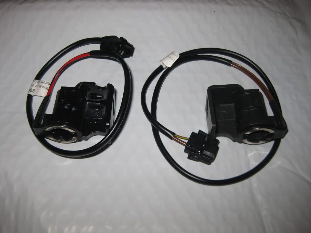 Trunk Lid Stoppers. These limit the upward swing of the trunk lid such that it cannot make contact with the hardtop and damage either component. Depending upon your build date, you will either need two of the 51240309364 stoppers at $4.20 each, or two of the 51248230139 stoppers at $5.03 each. See Item(s) # 9 in the RealOEM diagram. ** Note that most vehicles will NOT need the "Hardtop wiring harness retrofit kit" listed as Item # 11 in the RealOEM diagram. TOOLS NEEDED: You will need a Torx # 40 wrench/driver for removal and replacement of the support bolt, and a Torx # 20 for one of the six screws that fastens the trim. The bolt is TIGHT, so a Torx # 40 on a socket is ideal, but anything that provides good leverage for sufficient torque will work. You DO NOT want to strip this bolt! Note that the tool pictured on the right is OK for the # 20 trim bolt, but is NOT heavy duty enough for the # 40 bolt. 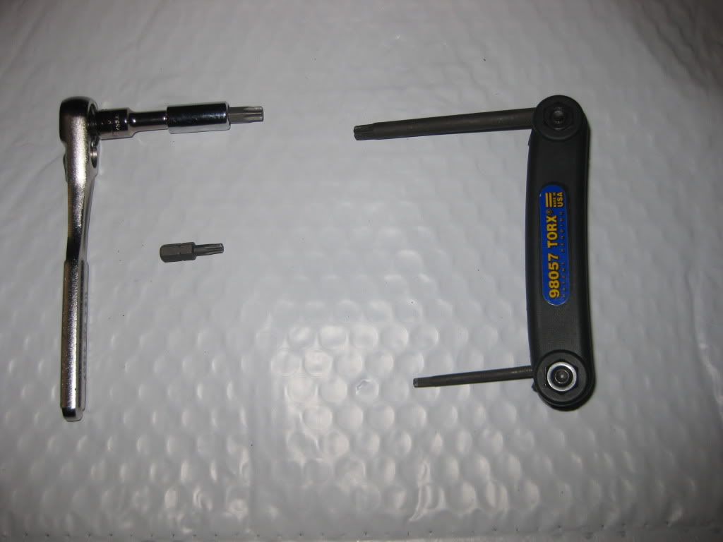 Implements to gently and safely remove the Subwoofer Grill and other trim. While flat bladed spatulas, screwdrivers, etc. will work, the $15 Actron CP5011 Panel, Trim and Molding Removal Set is ideal. (http://www.amazon.com/gp/product/B00...ef=oss_product) 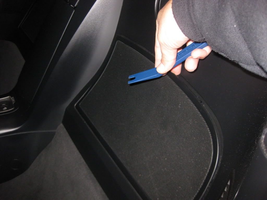 Small/medium vice grips, for bending out of the way the sheet metal that prevents full removal/re-installation of the bolt. Hard to see from the picture, but the chrome vice grips on the left are bending a piece of sheet metal that partially obstructs removal of the bolt seen in the very middle of the picture, and in a close up further down. 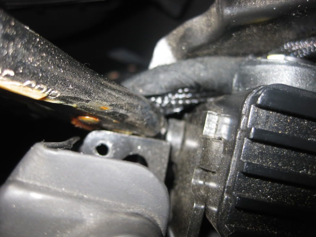 For reference purposes (i.e. NOT a tool needed because it's already installed on the car), here's a picture of the Torx # 40 bolt that needs to be removed for removal of the "dummy" posts, and then used to install the "Prep Kit" posts. When I refer to "dummy posts", which are pictured as the first image under “Procedure” below, I mean the hardware that was installed at the factory if the car WAS NOT ordered with the $75 hardtop prep option. If it WAS built with the hardtop prep option, then you shouldn't be here. These two pieces need to be removed and can probably be discarded unless, like me, you keep everything. 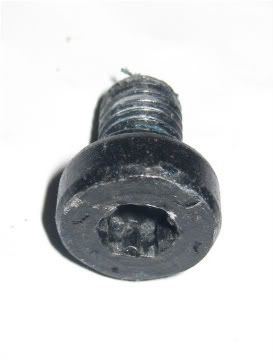 Phillips Head Screwdriver, for removing the screws from the subwoofer cavity. 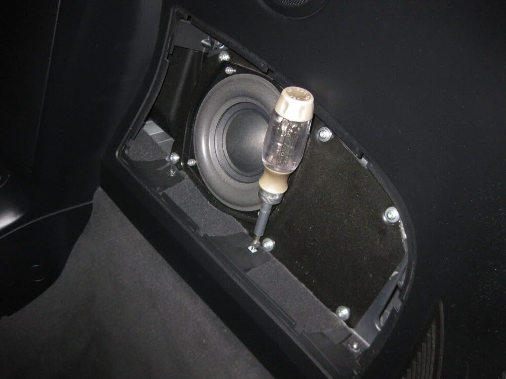 Two small flat bladed screwdrivers, for removing the rubber molding from the factory-installed “dummy” non-operational support. Difficult to see in the picture below, but the permanent outboard rubber gasket (seen better in the below picture with the Dremel, shown just to the right of the tool) is clipped to the top of the "dummy" support post (and will be re-clipped to the top of the new prep kit support post). The white plastic clip actually sandwiches a retainer on the support post, and serves to keep keep the upper rubber gasket/molding attached to the post. It simply presses down onto the post, but must be spread apart for removal. Wedging a small flat blade on each side facilitates removal. 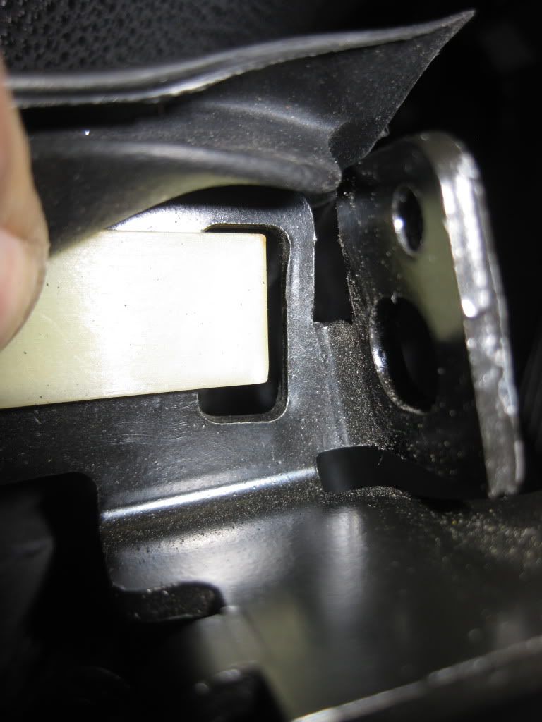 If needed (and you won’t know until you get in there) a Dremel or file to enlarge the fitment hole for the support. Neither of my new supports would fit until I enlarged the upper hole only a fraction of an inch with the Dremel, but others have had to remove as much as 2mm. Most have not had to remove anything. 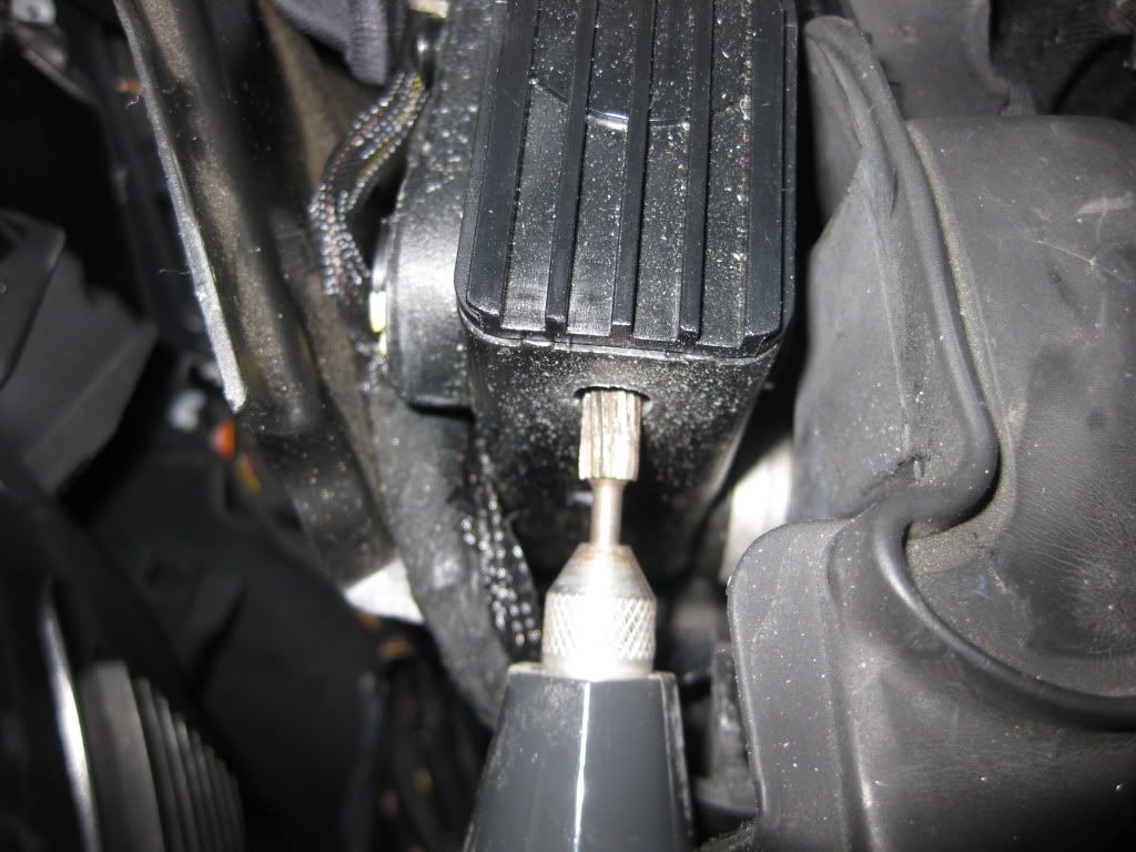 THE PROCEDURE: The objective is to remove the two "dummy" support posts pictured below, and replace them with the "prep kit" posts pictured above and from a different angle below. 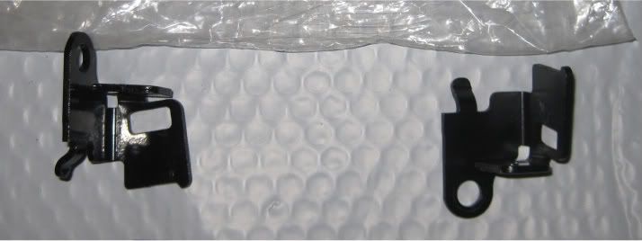 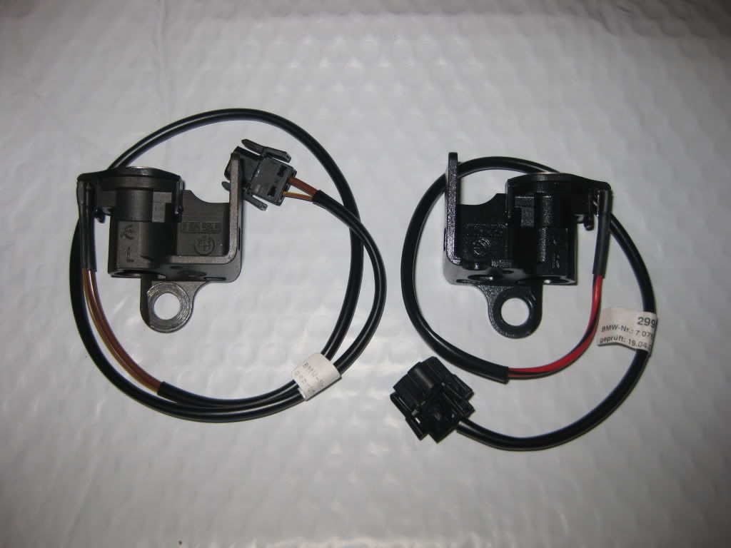 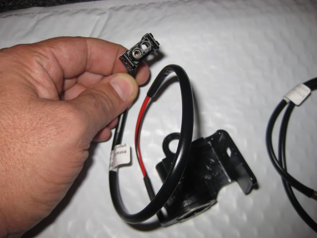 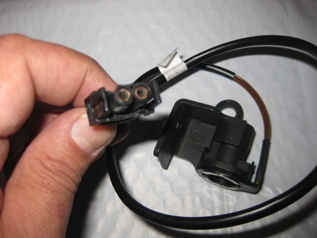 Additionally, the wiring from the two new posts must be connected to the existing wiring in the car. The area where the posts are located is immediately behind each door. In the first picture of the driver's side area, taken from above shooting downwards on the area, the front of the car is to the left of the picture (see the door lock) and the plastic trim piece is installed to cover the existing "dummy" post. 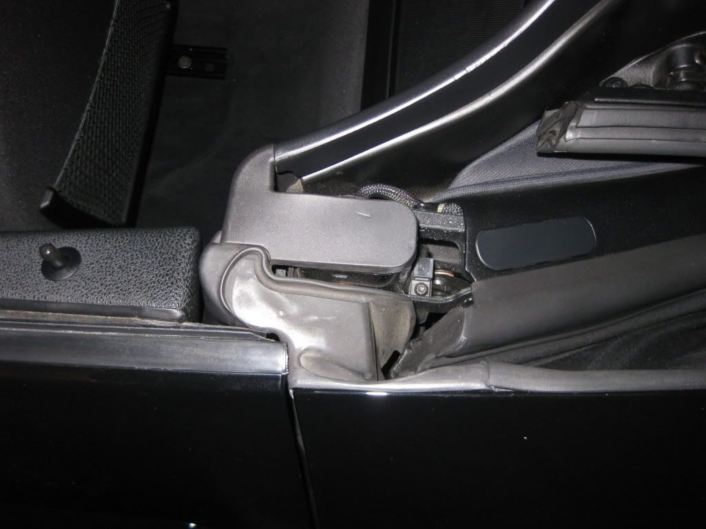 In the next picture, the plastic trim piece has been removed, showing the area where work will commence. All "business" will be conducted to the left of the permanently installed "stopper" component (with the five horizontal lines). Yes, things are a bit tight. You can partially see the existing dummy post to the lower left of the stopper. 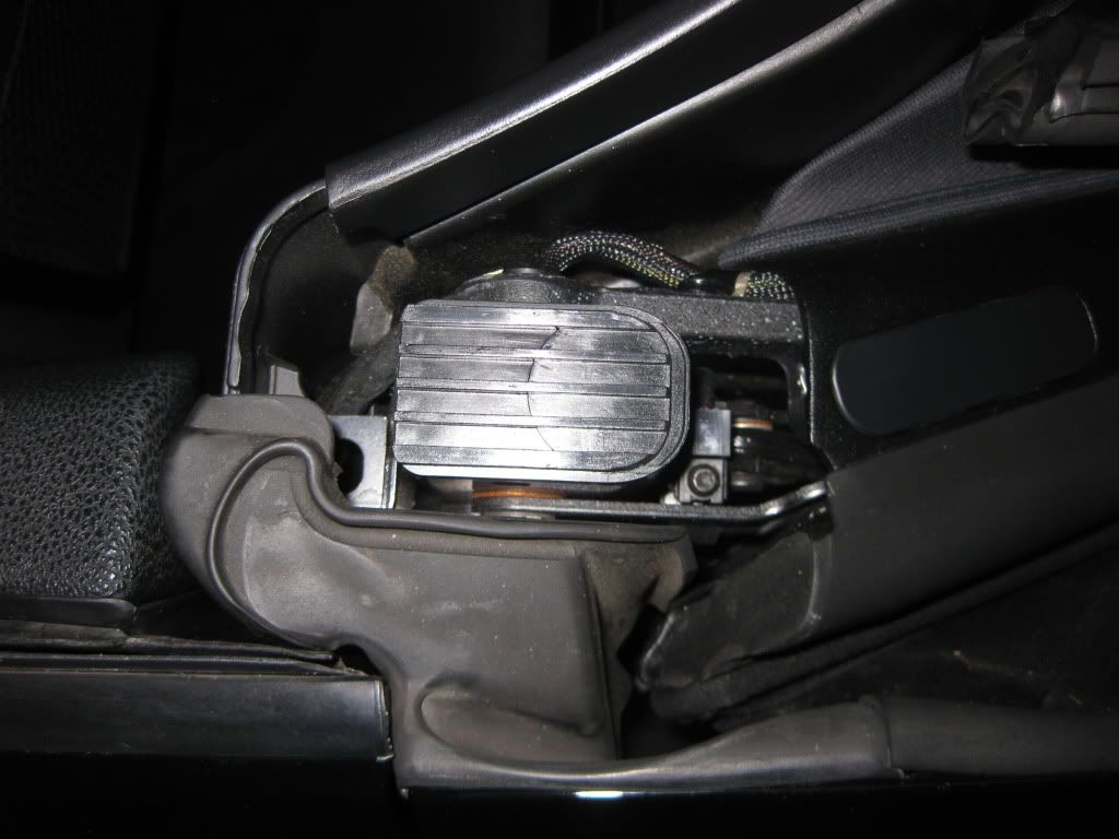 After work is completed on the driver's side, we want the same area to look like this (without the plastic trim piece first, and then with it installed). In the first picture, the rubber gasket has not yet been attached to the new post, so it's kind of hanging to the side at an angle to the new post. It simply presses down and clips permanently onto the post (you can actually see the raised piece where it will clip down onto). 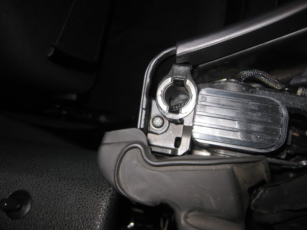 And here it is with the gasket clipped to the post and the plastic trim attached. 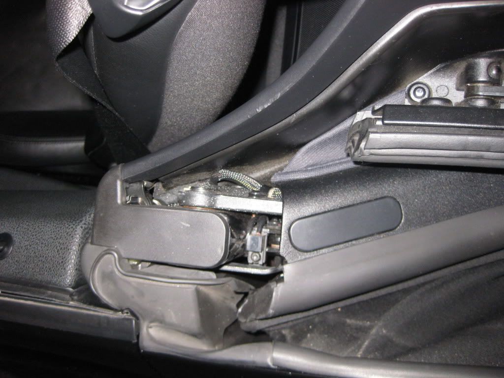 And finally, looking from the back of the car forwards. See the wiring to the right of the new post? Again, the post is mostly covered by the plastic trim, which just pops off or on (for a finished look when the hardtop is not installed). 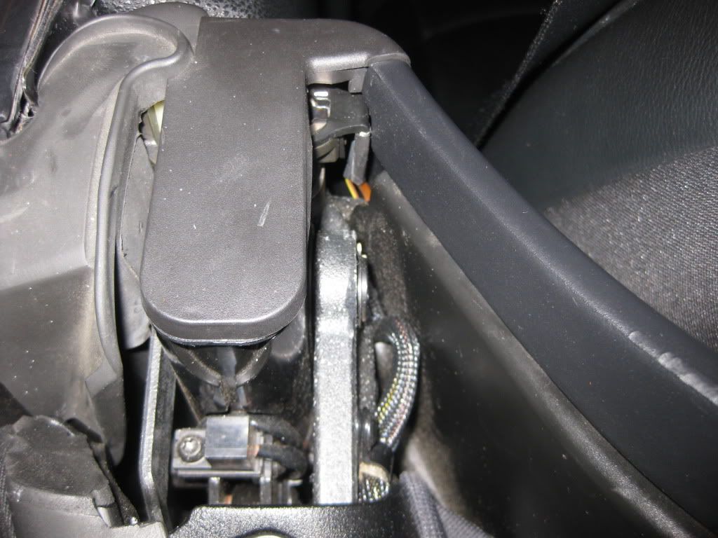 PREPARATION OF WORK AREA & REMOVAL OF DUMMY SUPPORT POSTS First, we need to move both seats all the way forward, and tilt them as far forward as possible. Re-route the seat belts so that they are out of the way. space is at a premium here. 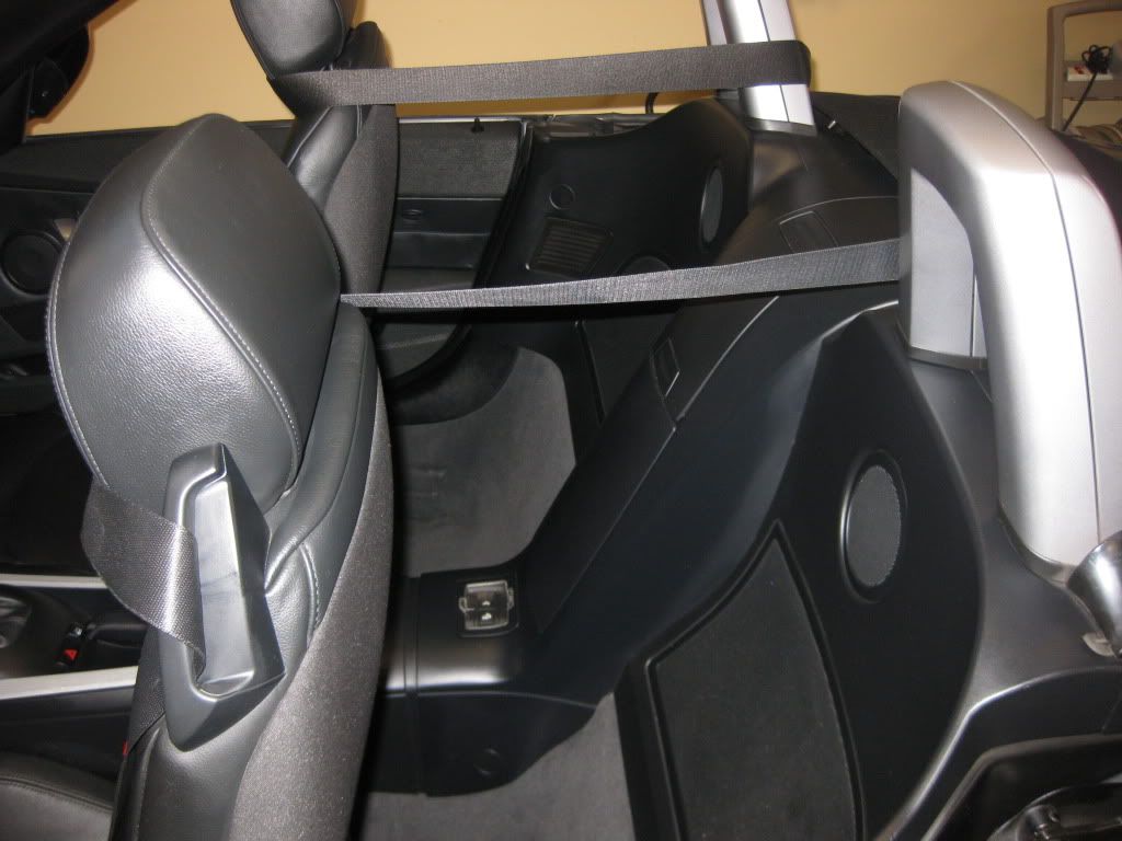 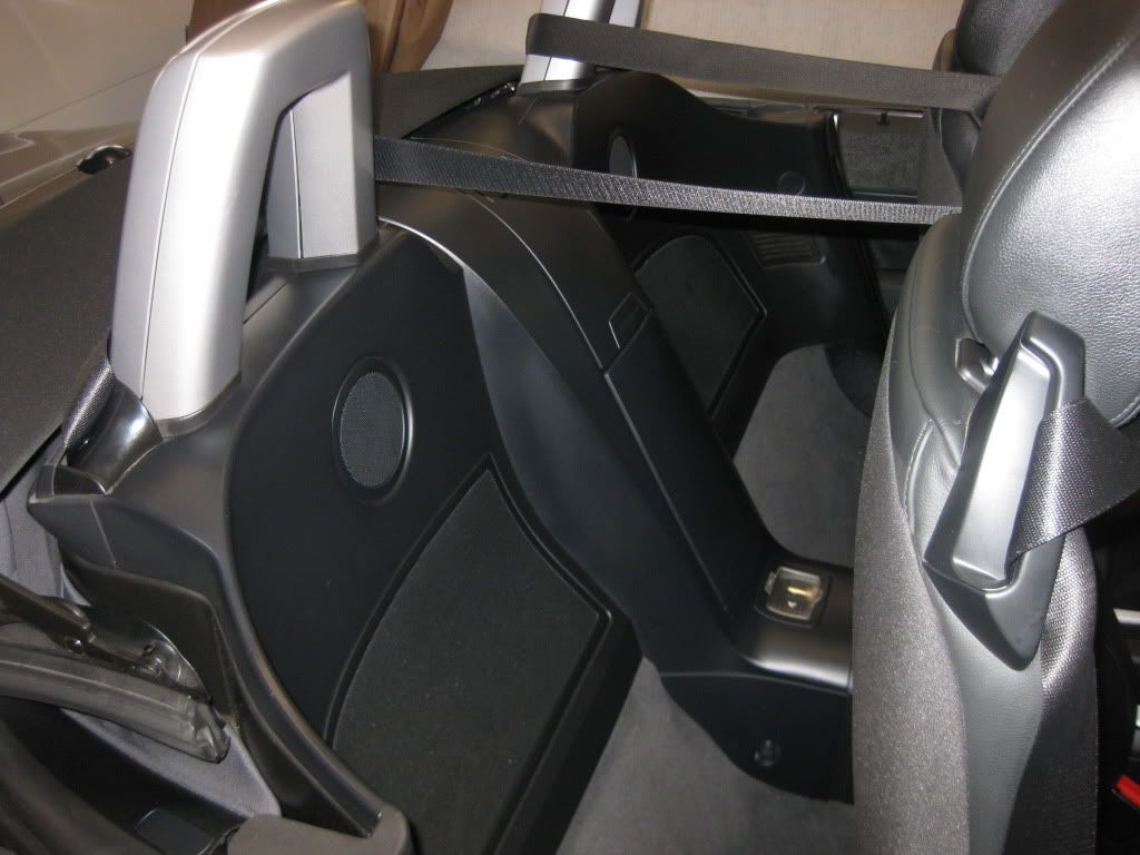 We'll start on the drivers' side first. The passengers' side will actually be easier. Pull off the plastic trim piece, if installed, to expose the stopper and the dummy post. 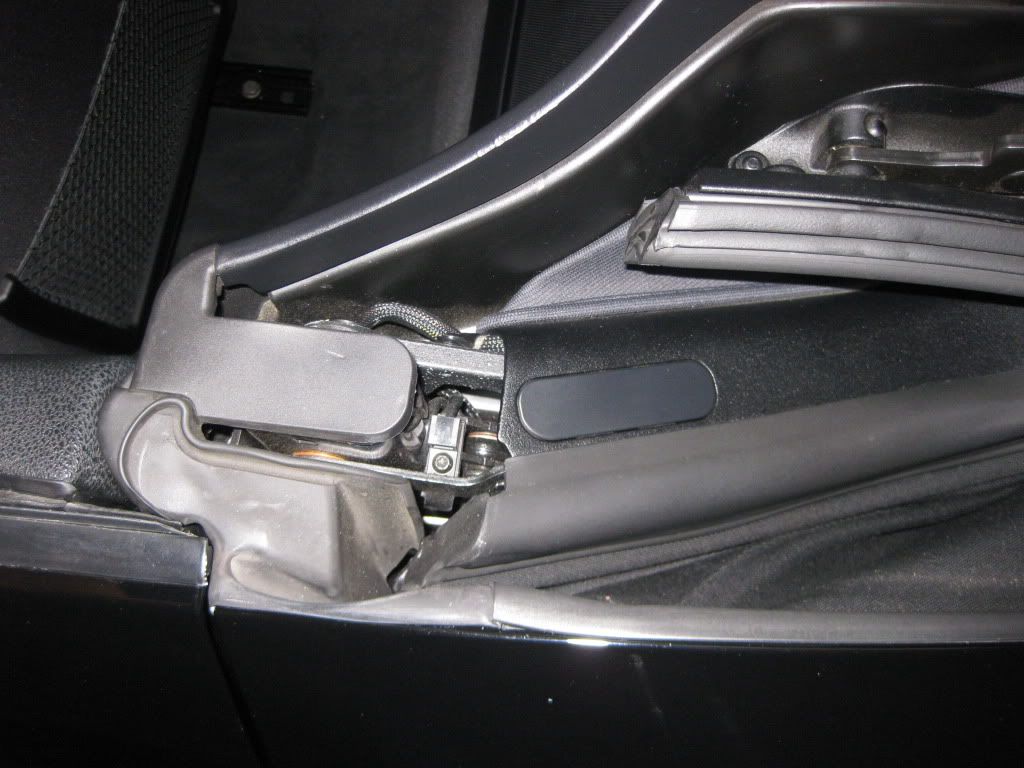 Next use an appropriate tool to gently pry the Subwoofer grill from the interior panel. It is held in place by 6 or 8 friction fasteners. You will hear them pop out. Once removed, the speaker cavity will be exposed. 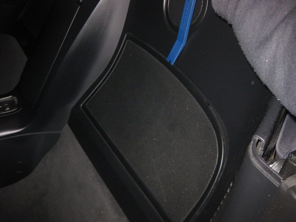 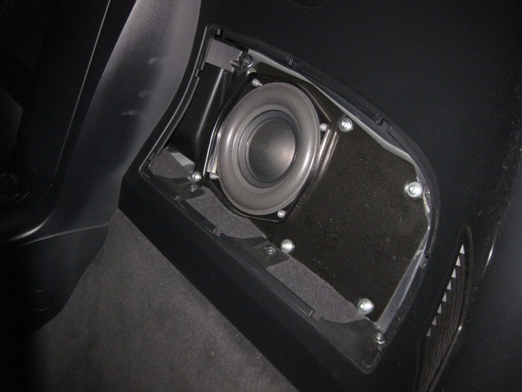 Now, remove the five Phillips head screws (three on the bottom, two in the top corners) that secure the panel to the frame. Do NOT remove the other screws that fasten the actual subwoofer to the frame. At this point, the panel is still secured by the Torx # 20 screw up near the dummy post. It faces DOWN into the frame, at the front corner of the panel in the dummy cavity. Remove that screw. 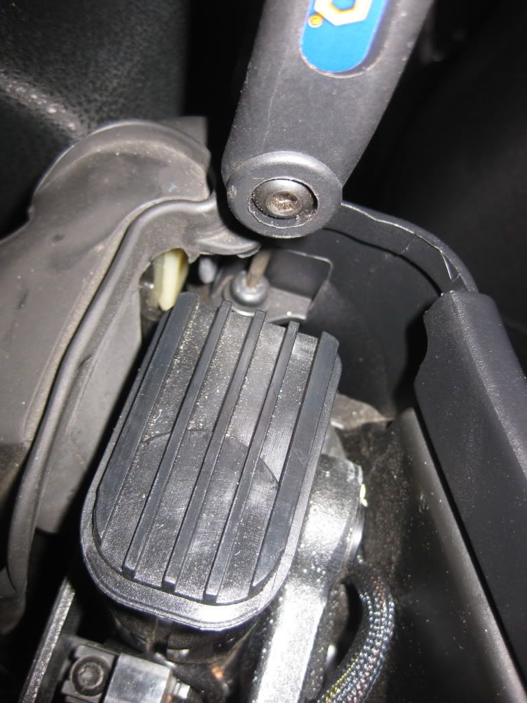 Now, the panel can be manipulated. IMPORTANT! Only move the panel the bare minimum necessary to gain access to the harness behind it. I pulled mine partially out of its positioning under the center storage console, and it was a pain in the A$$ to get it back. Literally, this was the most difficult part of my job -- and it shouldn't have been. The panel flexes, and you should be able to get to the harness without disturbing the positioning too much -- especially if you have small arms to gain access. (My forearms are grotesqeuly overdeveloped from steroids, free weights and Muscle Milk, but that's another story). 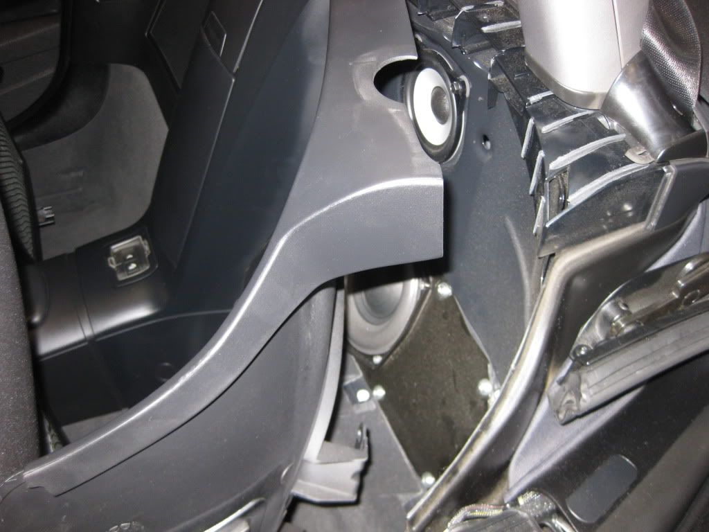 In the next shot, you can begin to see the wiring harnesses behind the panel. 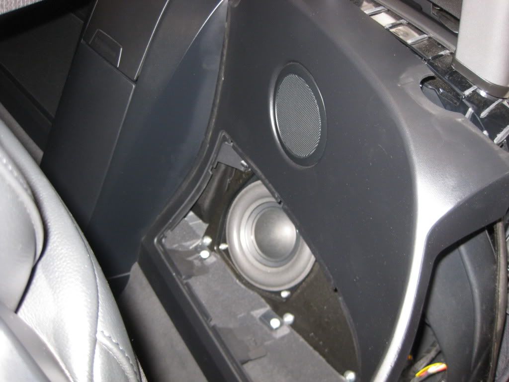 PREPARING THE FACTORY HARNESS FOR CONNECTION WITH THE PREP KIT SUPPORT POST PIGTAIL Now, you need to locate the harness connector that the pigtail on the Left prep kit support post will plug into. A pretty good indication will be the wiring colors. Just like the pigtail, the harness connector has a Brown and a Brown/Yellow striped wire going into it. Note that it abuts and is fastened to another white harness, and both are in the general vicinity of a white electrical component box. See the pictures. Note the brown wires feeding UP into the harness.  Yep, there she is! 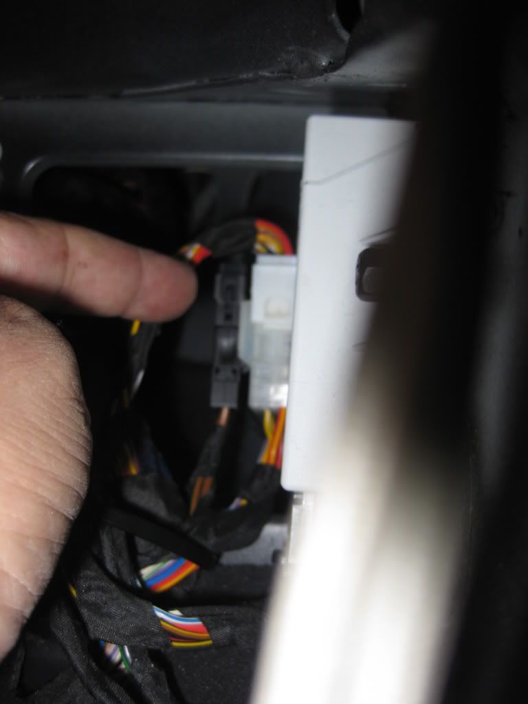 If you still haven't found it, find this box and then look to the left of it. 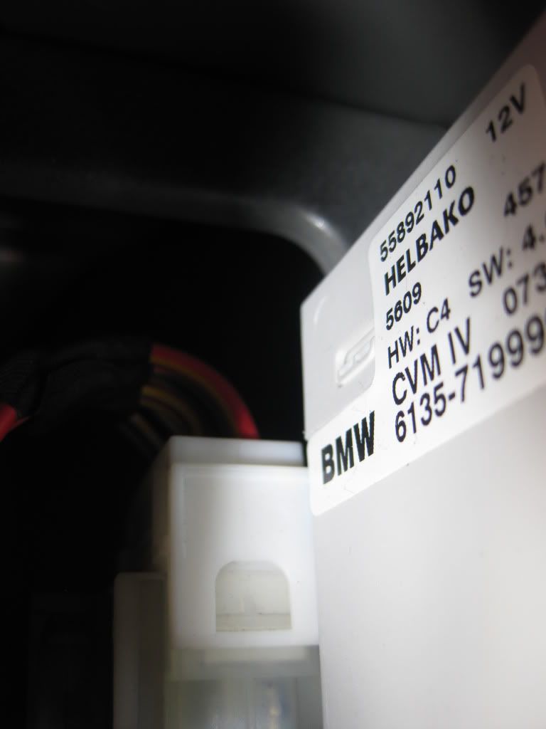 Once you have located the harness, IMPORTANT!!, you must remove the cap that protects and covers the harness. If you don't, the pigtail from the support will not fit, and you will not be happy. Squeeze the sides of the protective cap (it takes dexterity) and remove the cap, leaving the harness uncovered and ready for the pigtail. Here, I've just removed it. See how it is empty, i.e. no metal contact points inside? 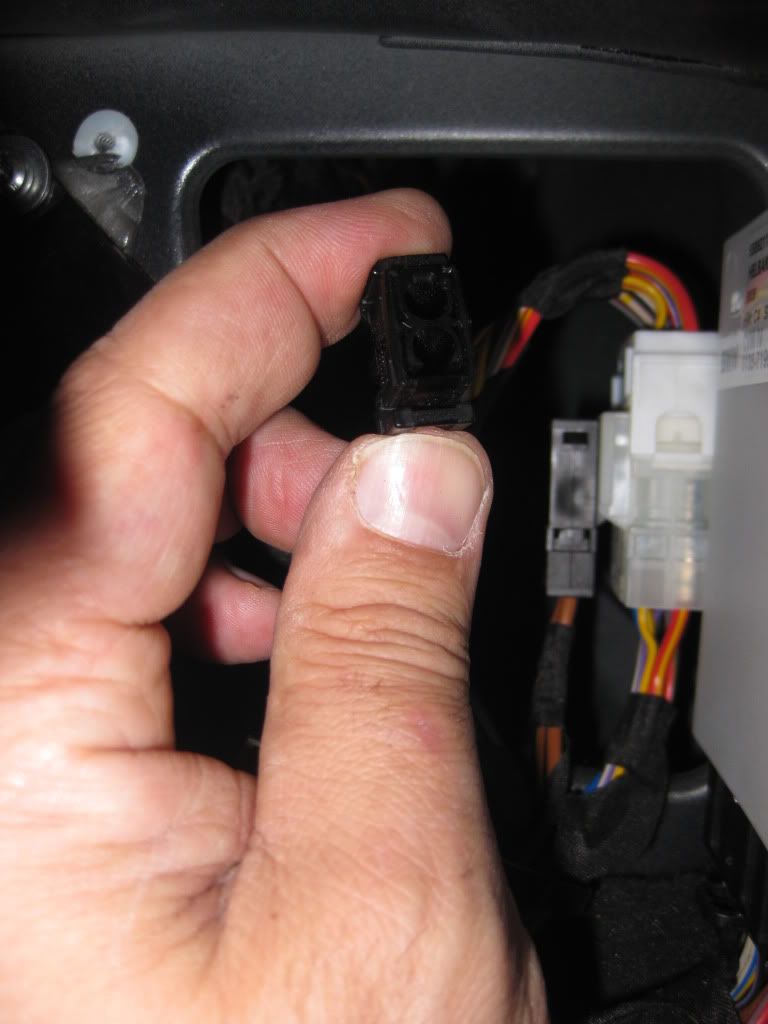 Removed, the two caps (shorting plugs) look like this: 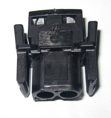 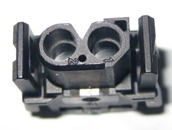 INSTALLATION OF THE PREP KIT SUPPORT POST WITH ELECTRICAL CONNECTOR Time to head back up to the support cavity. The first task is to remove the dummy post by removing the Torx # 40 retaining bolt. Previously pictured above, this bolt sits horizontally, with the head of the bolt towards the front of the car and the shaft pointing towards the rear of the car. The dummy post mates to the existing frame, and is held in place by this bolt. See it down there? 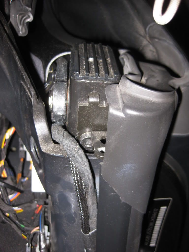 A little closer. 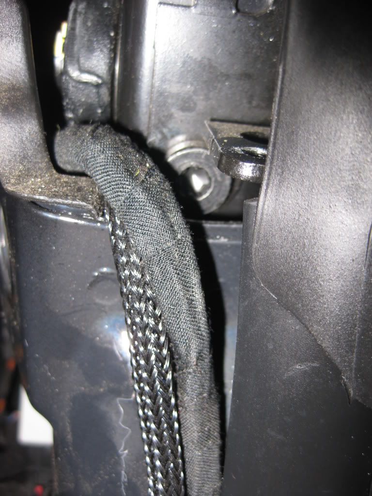 Should be a simple matter of backing out the bolt, right? But it isn't. First, the strongest guy in Spartanburg put it in and, unless you have forearms like mine, we'll need a socket and some torque to get it started. Second, a strip of painted sheet metal protrudes up just far enough to block complete egress of the bolt -- so it needs to be either bent (best option, IMHO) or cut away just far enough that the bolt (which thankfully is short) can be removed. I manipulated vice grips into the gap and then bent the piece down. Though the pictures aren't terribly descriptive, you'll see the bites left from the grips, just under the bolt in the second picture. 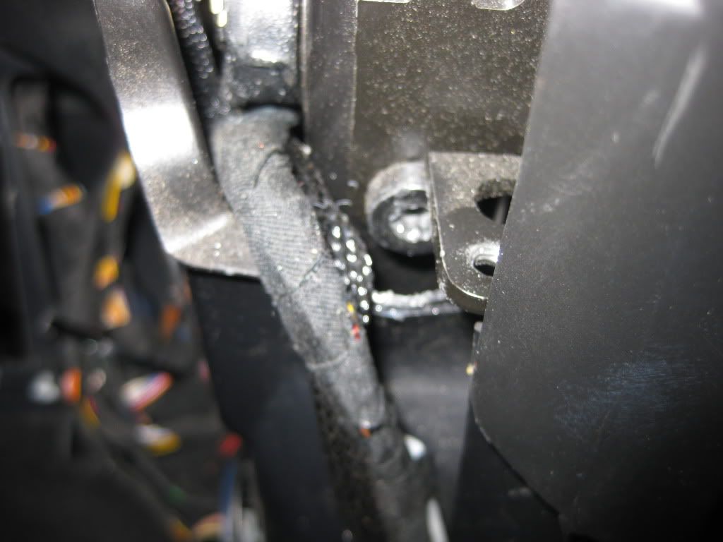 Once the bolt is removed, the dummy post can be removed. Note the little tang that is at the top of this picture. This fits into a second hole just above the bolt hole. The prep kit post also has this tang, and it is this top hole that MAY have to be enlarged for the new post to fit. 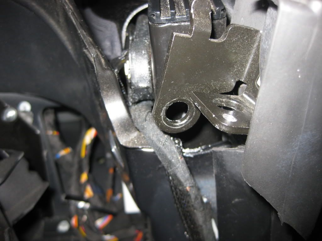 The dummy post will still be attached to the rubber gasket (explained and pictured above) by means of a white clip. Use your two flat head screwdrivers to remove the clip from the dummy post, and then remove the dummy post itself. Now you have exposed the area where the new support post will go. Note the two holes. Bottom is for the bolt. Top is for the tang, pictured on the back of a new support post (and in the closeup, actually the passengers' side post with red wires, so don't be confused). 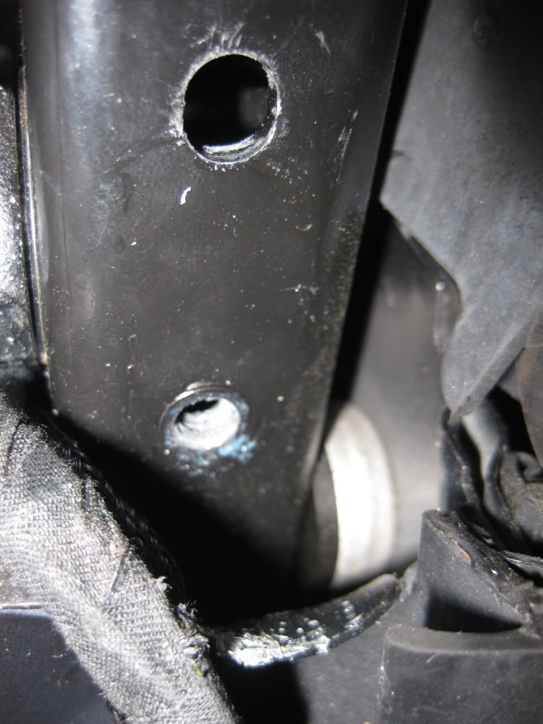 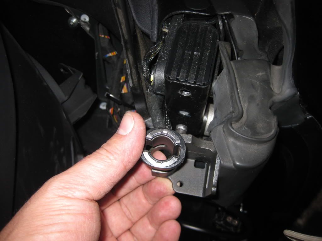 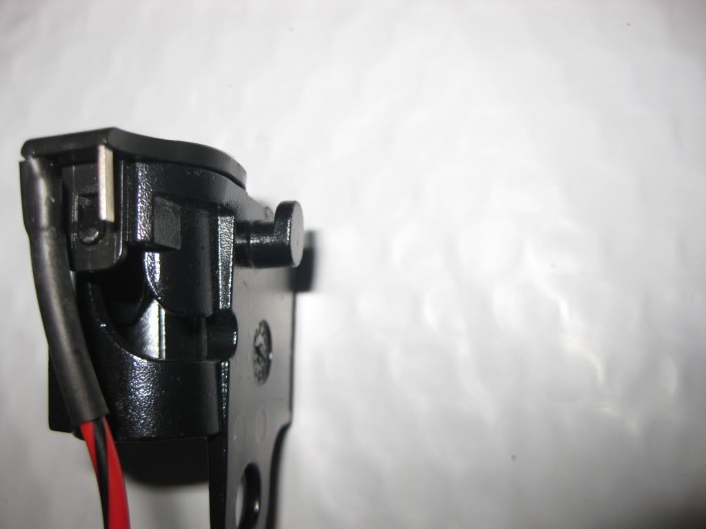 INSTALLATION OF THE NEW PREP KIT SUPPORT POST As stated above, the tang may not allow complete seating of the new support post unless the top hole is enlarged. If necessary, grind away a little at a time with your Dremel, checking for proper seating. Once the new support seats, fasten it with the bolt. Note the pigtail hanging outside of the cavity into the passenger compartment. 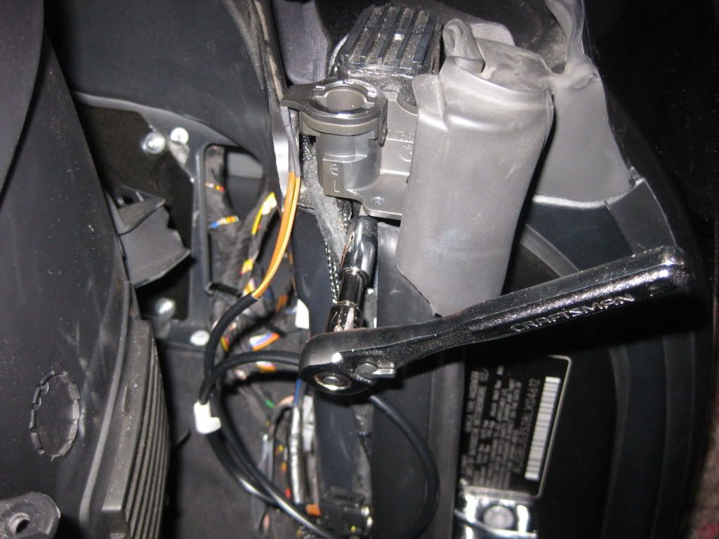 The pigtail is then fed OUTSIDE THE CAVITY (do not try to feed it within the cavity) under the panel and back to the harness. Plug it in. 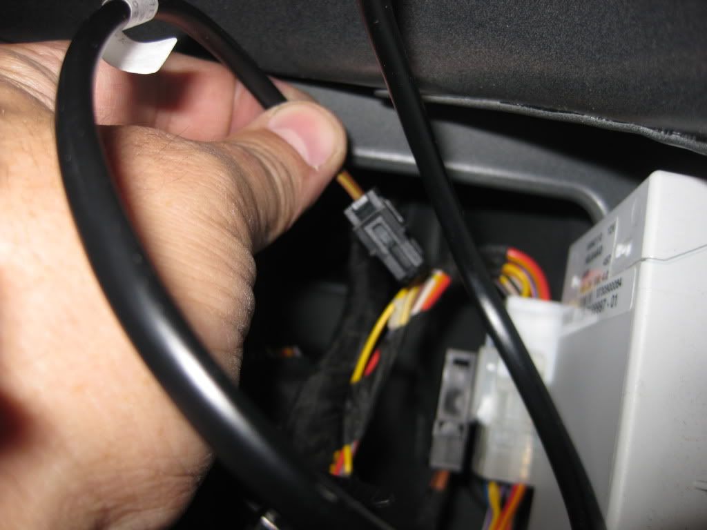 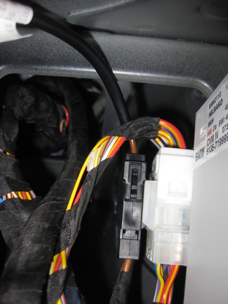 Now push the gasket and clip over the new support, tuck in/secure the pigtail wiring, replace the panel (Good luck with that!) and admire your work before moving to the other side. 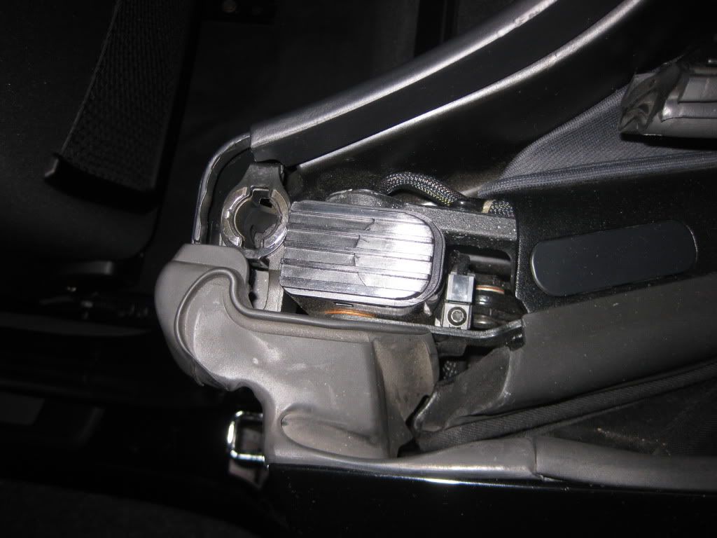 INSTALLING THE RIGHT / PASSENGER'S SIDE PREP KIT SUPPORT Well, the process is exactly the same, EXCEPT . . . 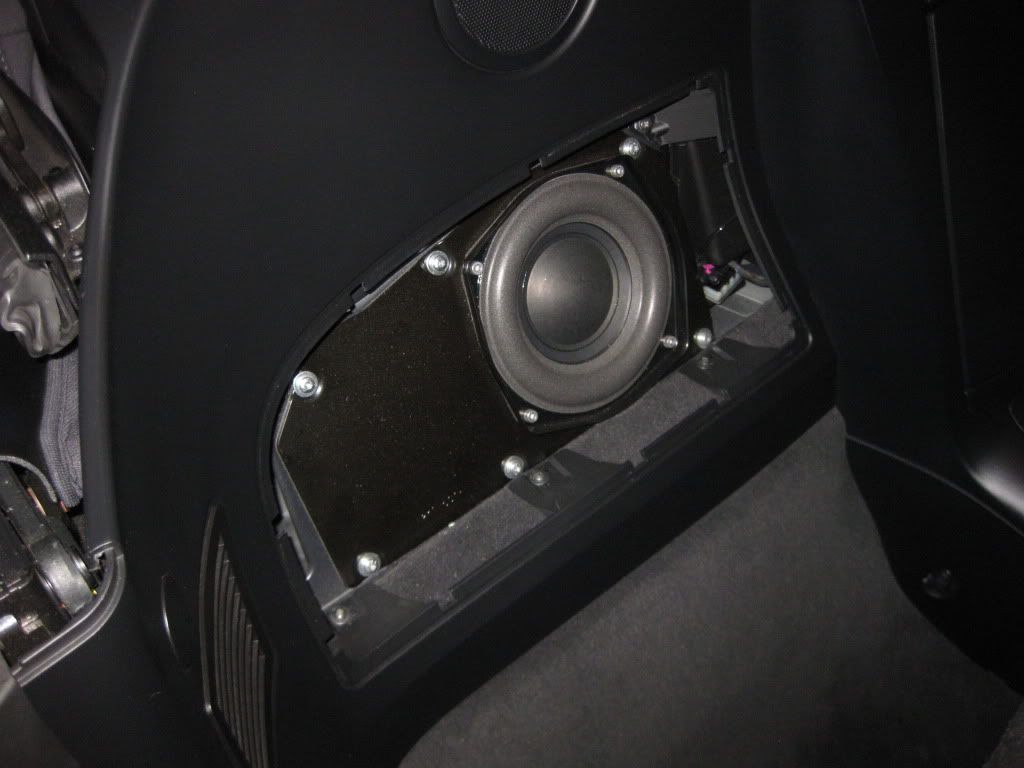 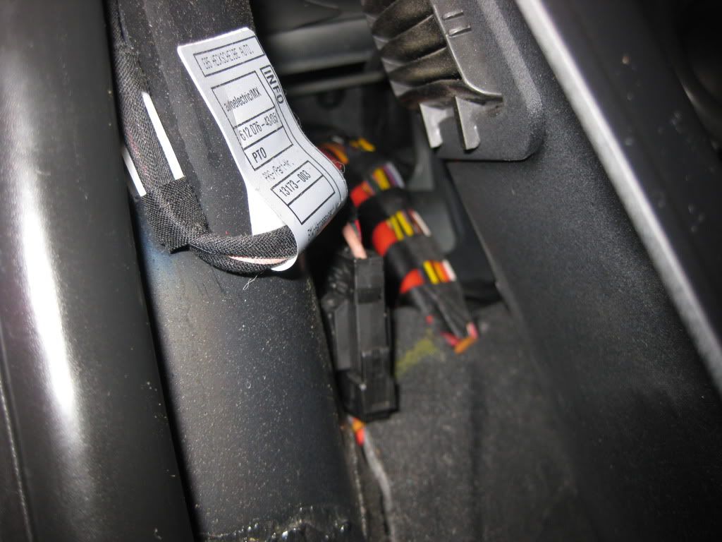 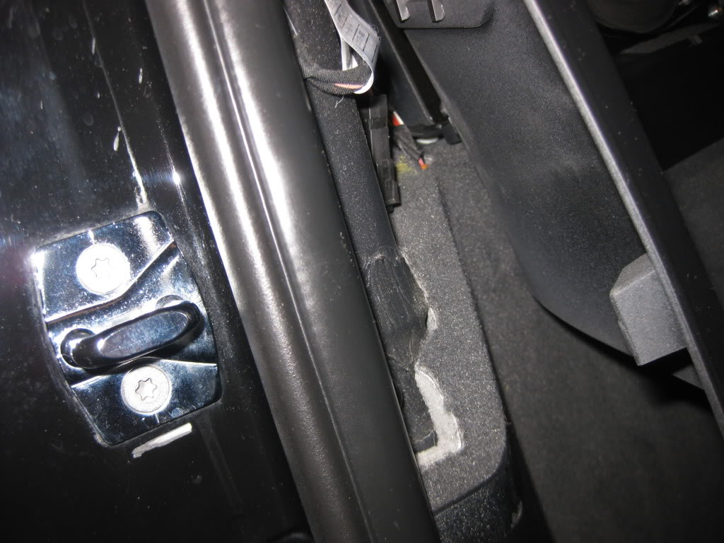 Yep, the harness is only about 8 inches back from the edge of the panel (reference the door striker in the pics), so you don't have to dig as much as with the driver's side. While you still need to remove the support cavity Torx # 20 screw, you may not need to remove all of the speaker cavity screws. (I didn't know that the harness was so accessible, so I removed all of the screws, but it isn't that onerous anyway). Again, identify the harness by the Red/Black stripe wire going into it. It also abuts and is BEHIND another harness (looks like that one has a pink and blue wire from the picture). It also has a safety cap that must be removed. Now, install the right side support using the same procedure as the left side, plug in the pigtail, put everything back together, and thank me later. Enjoy!! Kimolaoha 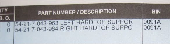 Last edited by Kimolaoha; 07-17-2014 at 09:51 AM.. |
| 12-16-2010, 12:02 PM | #2 |
|
Enlisted Member
6
Rep 43
Posts |
In response to those who have inquired via the various Fora and by Private Message, please note that my Hard Top is still enroute from Germany and I therefore cannot post pictures of my own car with the top installed.
However, while researching the prep kit project, I harvested several photos that were readily available on the web, and saved them. Unfortunately, I can no longer attribute these great shots, but am happy to post them here with thanks and credit to the original owners. Indeed, it was photos such as these that induced me to proceed with the project. Perhaps you will agree that the hard top is a stunning addition. Enjoy!! 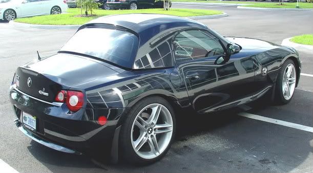 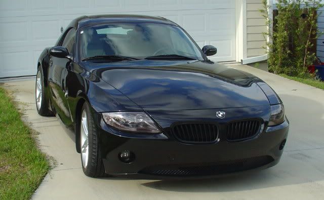  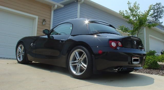  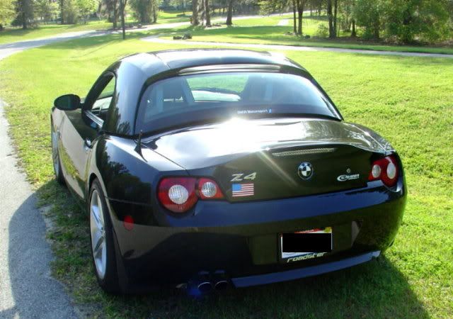 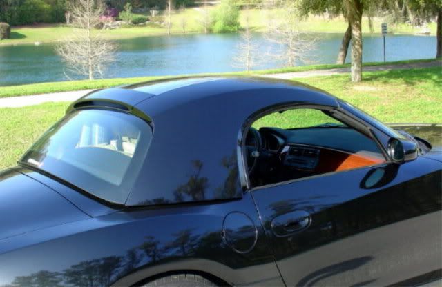     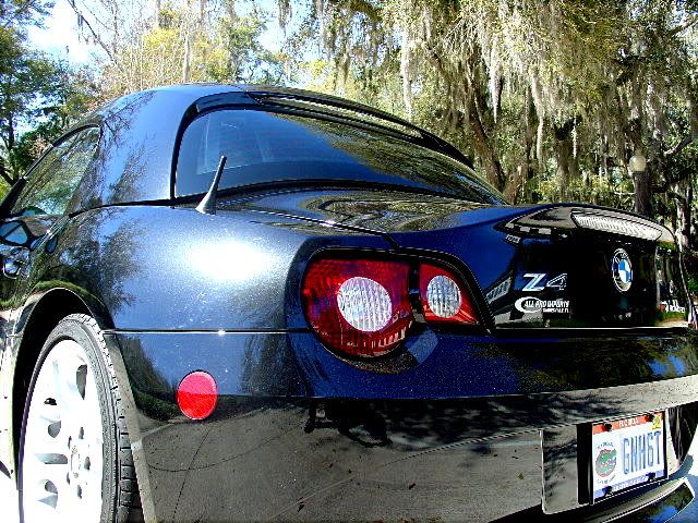 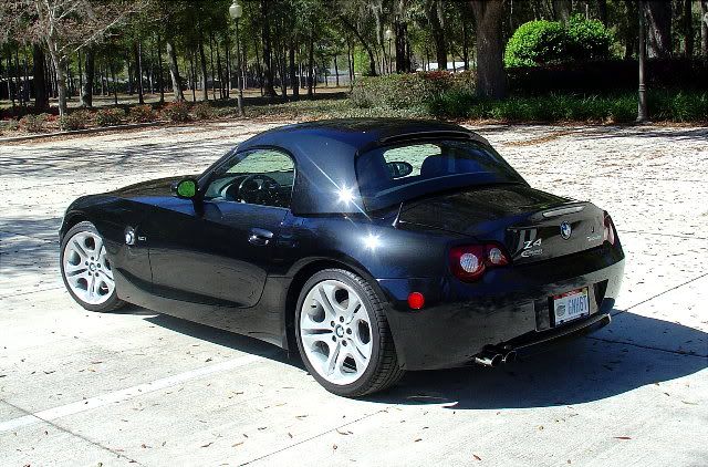 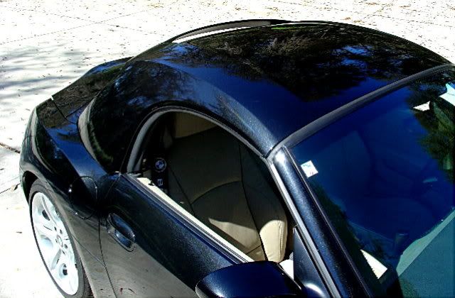  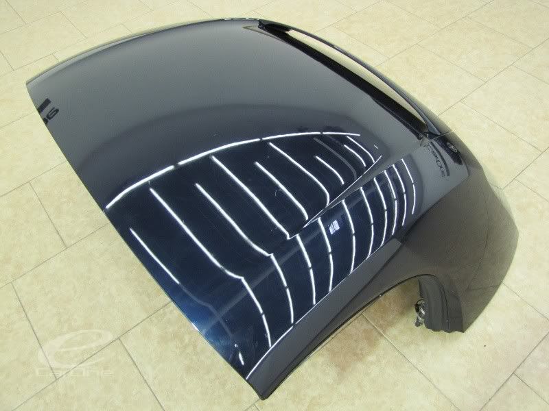 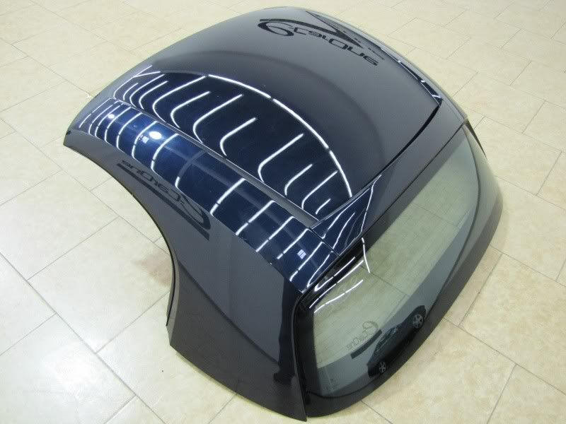 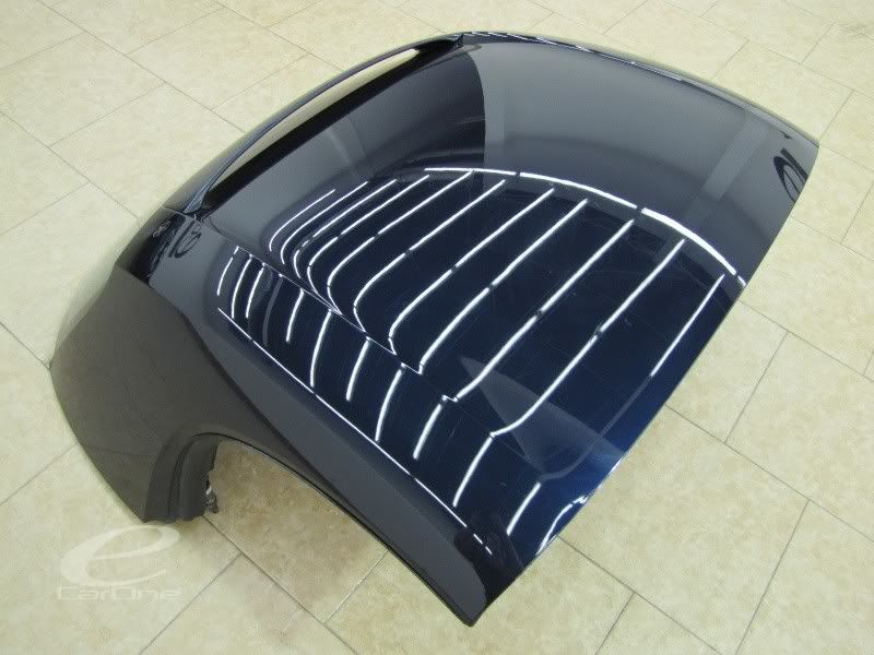 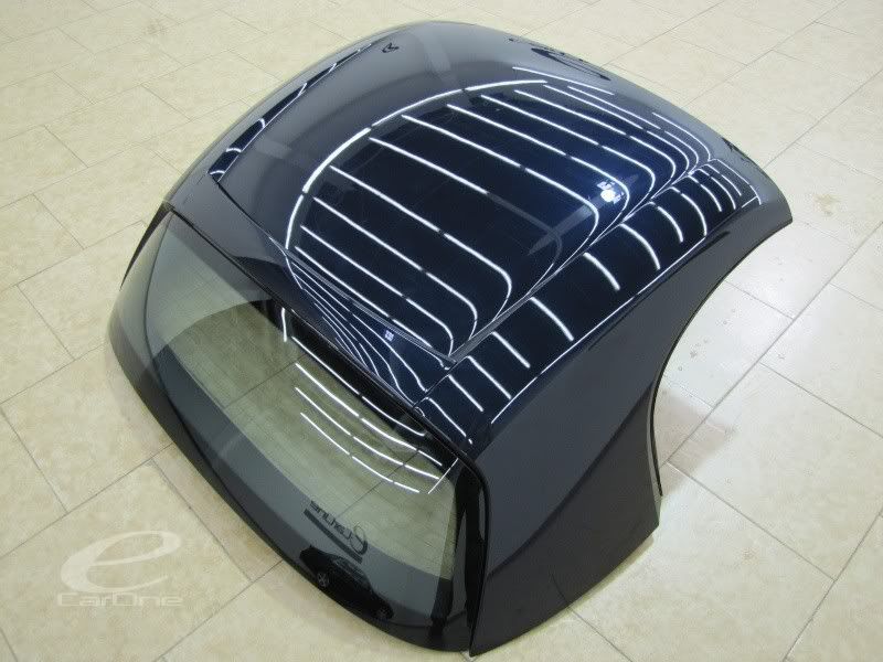 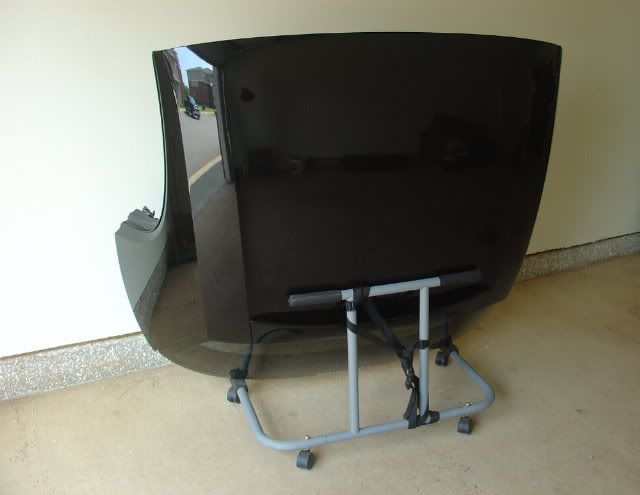 |
|
Appreciate
0
|
| 12-16-2010, 02:18 PM | #3 |
|
John 14:6


59
Rep 588
Posts |
Wow, awesome write-up
 . I wish this was available when I installed my prep kit and hard top. BTW, how much was your hard top? You won't believe the price I got mine for . I wish this was available when I installed my prep kit and hard top. BTW, how much was your hard top? You won't believe the price I got mine for  . .
__________________
 Mods: Eibachs/Konis, Eibach camber kit, JTD RSMs, 19" WedsSport SA67, Hamann headlight trim, Aero front bumper, Aero sides, AC Schnitzer side deflectors, Hella euro taillights, Hardtop, Dinan strut & supplemental bars, RD Sport intake, Dinan Stage 2 Software, RPI scoop, Bastuck catback exhaust, Radenergie CF engine cover...  |
|
Appreciate
0
|
| 12-22-2010, 10:32 AM | #5 |
|
Enlisted Member
6
Rep 43
Posts |
Here's the easy DIY for installing the trunk lift stoppers. Just slip the new ones over the old ones. Presumably decreases the upward movement of the trunk lid, but it sure isn't by much! Not convinced that it's even necessary.
See pics: The part number 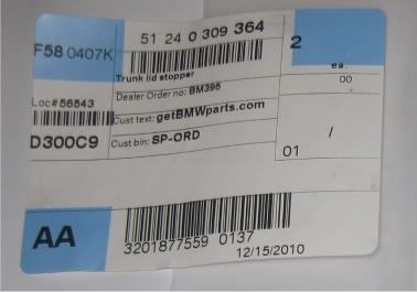 The two stoppers 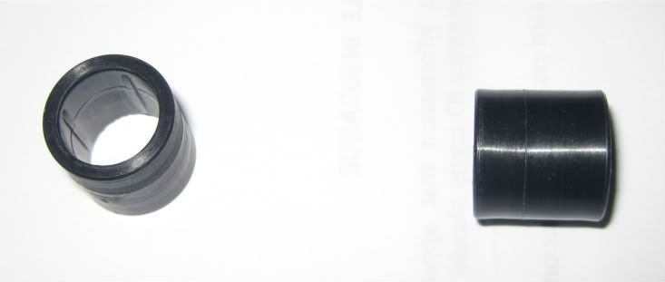 The left side post, before installation of stopper 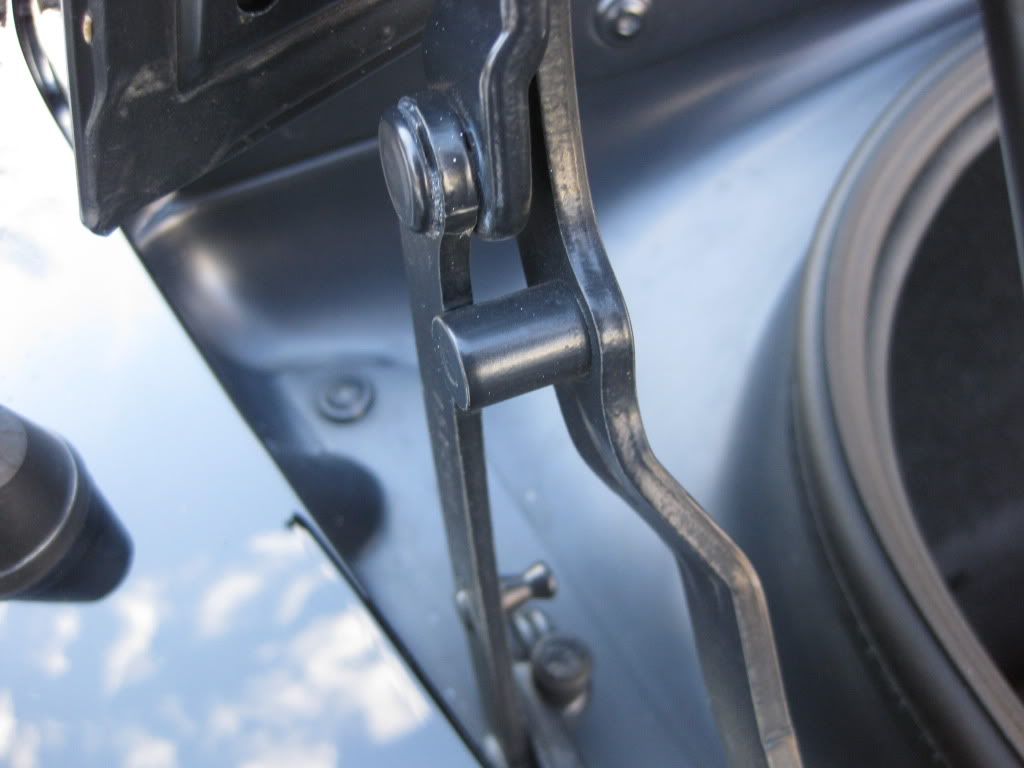 Closer 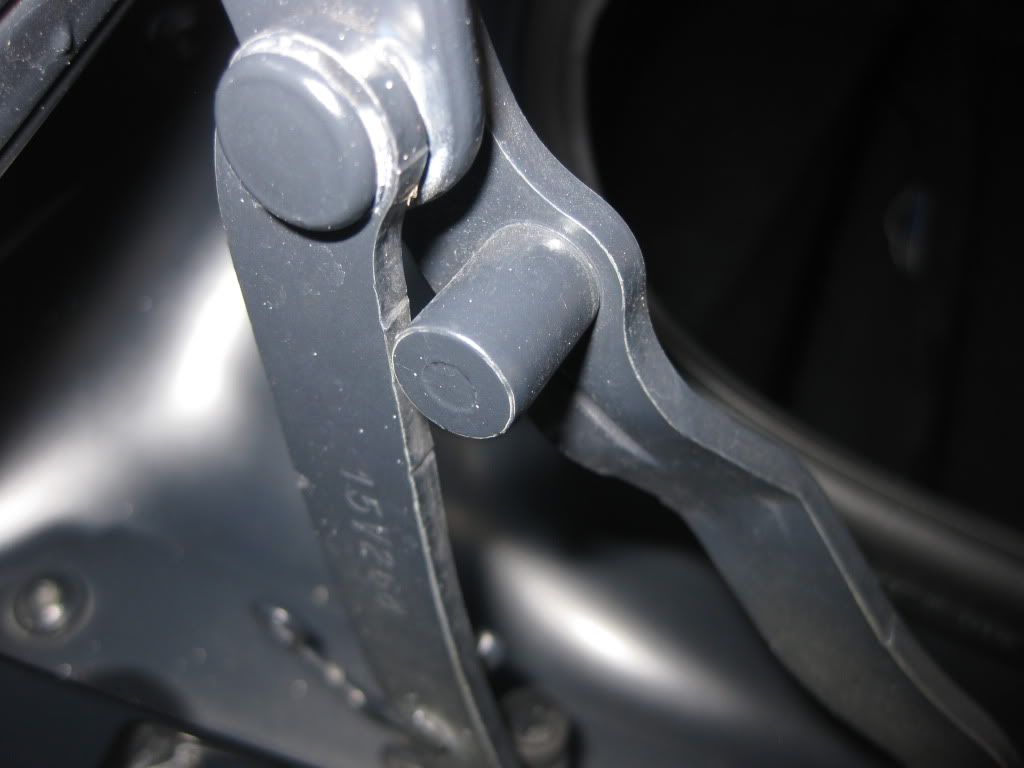 Left side post AFTER stopper was slipped on 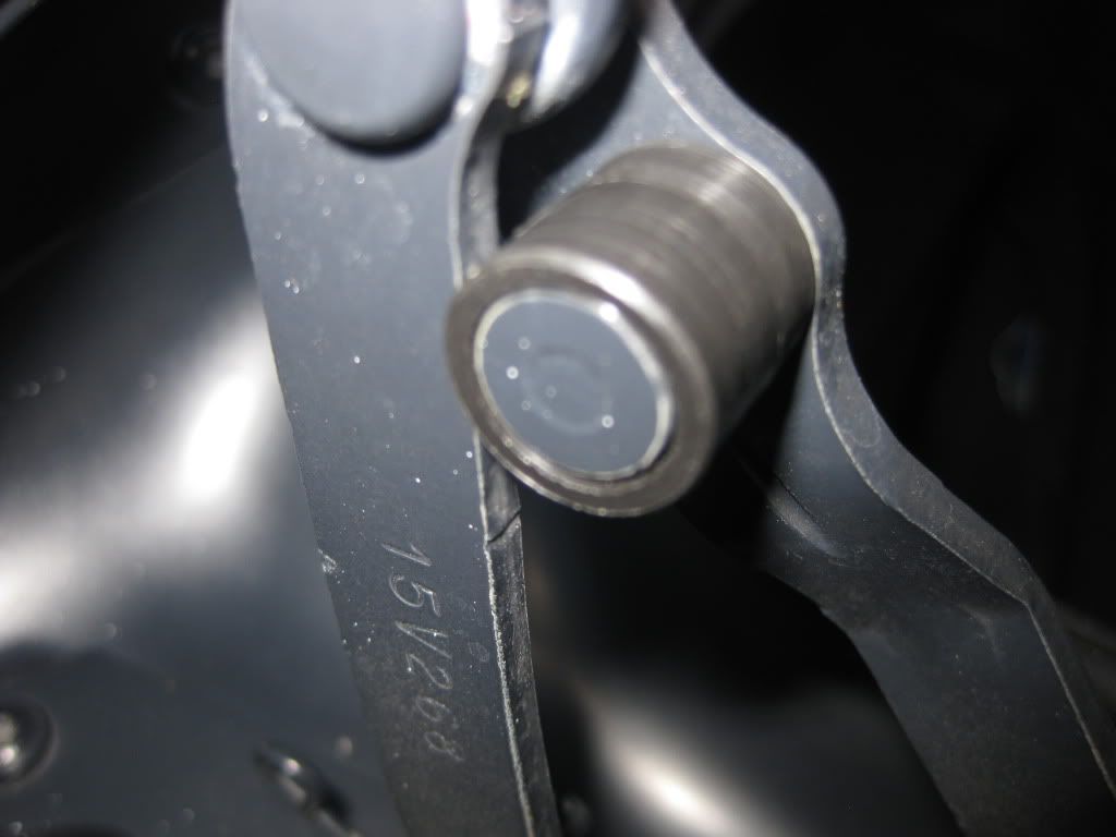 Right side post before stopper 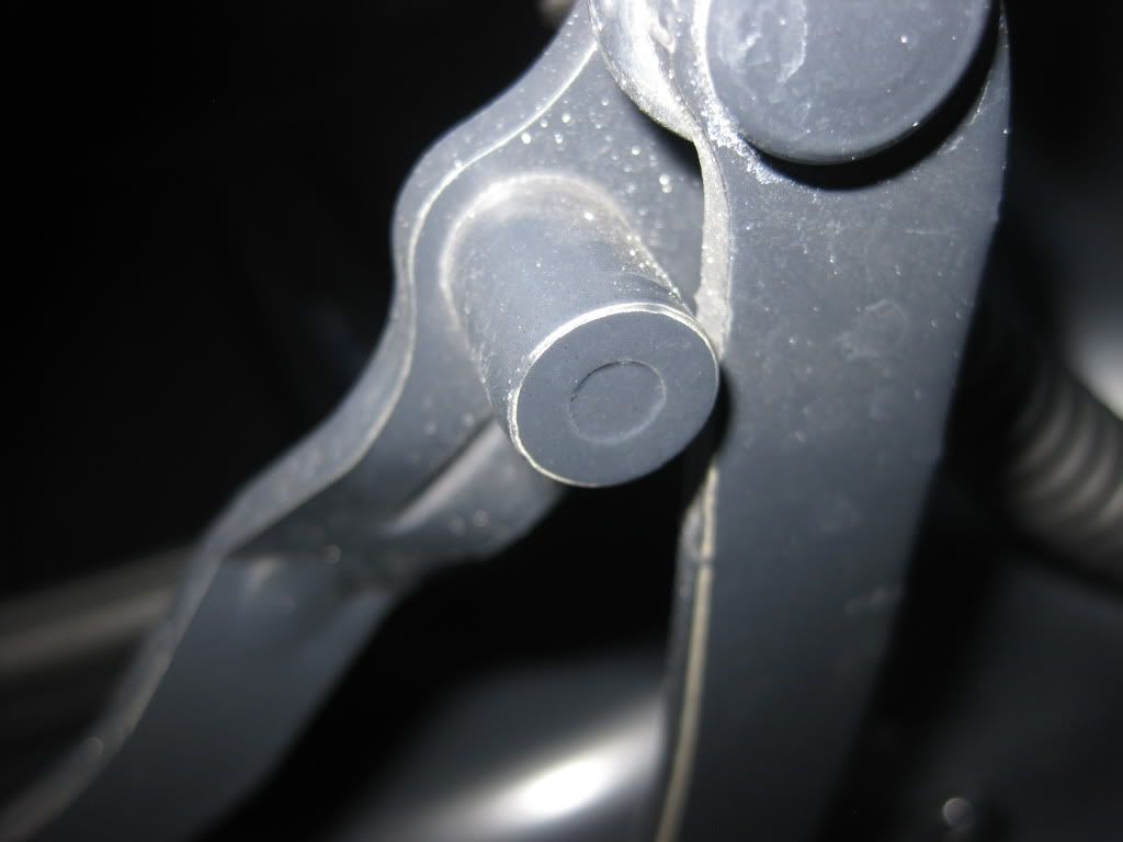 After stopper 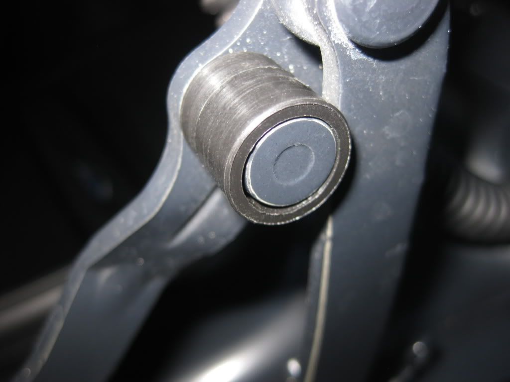 That's all there is to it. |
|
Appreciate
0
|
| 04-16-2011, 03:06 PM | #6 |
|
Lieutenant
 40
Rep 525
Posts |
OK, so the top just arrived (exactly 4 months after ordering it) and it is now installed on the car and looks fantastic.
It's raining cats and dogs here so I can't really do too much testing until later, etc., but here is what I noticed on the drive back from the dealer. While the windows do, in fact, go up and seat just fine with the hard top installed, the one-touch feature does not seem to be operating correctly. Specifically, (and this is true for BOTH sides,) once the one-touch is activated, the windows roll up automatically, but at the top of their travel they then immediately go back down, parking in about the the 1/4 up position. When the windows are going back down, the switch seems to be disabled, i.e. the window cannot be made to go back up until the downward movement is completed. However, if the window switch is HELD in the up position throughout the entire upward travel, the window will go all the way up and stay there. I also note that when the door is opened/closed, the normal slight up/slight down clearing movement of the window occurs. The immediate down window movement that I describe above is almost as if the safety (no pinch) feature is being activated, i.e. the top of the hardtop window frame cavity is sensed as an obstruction and the window immediately goes back down. I certainly can't imagine that this is the way it is supposed to function, and haven't tried the window park reset procedure (need to find it again), but can anyone shed any light on what may be happening here? I also have not figured a way to test if the rear window defog/defrost function is working properly since I currently have no fog or frost to remove. If anyone can suggest a way to test this, I'd be interested. Thanks
__________________
 |
|
Appreciate
0
|
| 04-17-2011, 10:13 AM | #9 | |
|
6 of Diamonds (ret)

82
Rep 566
Posts |
Quote:
If you dont want to do that you can try raising the height of the hardtop posts a little. See the attached pdf for the adjustment procedure. 6183EN.pdf By now you probably know exactly why BMW calls for the boot lid travel limiter mod. Even with the two limiters that lid gets really close to the Hardtop Glass. BTW thanks for the write-up. It helped me enormously when I did mine a month or two ago.
__________________
 2007 Z4Si(gone) 2007 Z4Si(gone)Couple E30 Verts (DD) 2003 330i 2011 E93 335is - current fav Last edited by BruceJ; 04-17-2011 at 10:27 AM.. |
|
|
Appreciate
0
|
| 04-17-2011, 02:33 PM | #10 | |
|
Lieutenant
40
Rep 525
Posts |
Quote:
Have you been able to test the defrost/defog function on the hardtop window? As it turns out, I went out this morning intending to try the reset procedure and, surprisingly, I didn't have to -- as the windows seem to be functioning correctly now. Go figure. For those who might need it in the future, though, I've appended the reset procedures from my owners manual (model year 2008) as well as another version of the same method (borrowed from a post I found on one of the forums). Finally, after waiting four months for the hardtop, it was installed on the car for less than 24 hours before it went into winter storage -- as it is now hanging on my garage wall until next winter  The Window Reset Procedure From the 2008 Z4 Owner's Manual: Ensure that the doors and the Roadster's convertible top are closed before initializing. 1. Open the window completely. 2. Press the switch 4 times within approx. 10 seconds. Afterward, perform the following procedure twice for each window: 1. Close the window completely by pulling the switch. 2. After the window is closed, keep pulling the switch for approx. 2 seconds. 3. Open the window completely by pressing the switch. The Same Window Reset Procedure courtesy of a BMW tech on another forum: Initialization is performed on the power window switch of the relevant door. Requirements for correct initialization: Initialization with engine running Convertible top, doors and windows closed Initialization comprises: Erasure of initialization Reinitialization An initialization must be performed: In the event of malfunctions, e.g. no one-touch control function, no opening or if available no comfort function is possible After the power window drive has been replaced After work is carried out on the power window mechanism After a power supply interruption, e.g. disconnection of the battery or disconnection of the power supply to the door After the door window glass has been removed and installed or replaced After adjustment work on the door window glass After adjustment work on the convertible top After replacement of seals Erasure of initialization: Open door window glass fully Operate power window switch in "Open" position four times within 10 seconds This erases initialization of the power window, anti-trapping protection and toll function are inactive. Check whether one-touch control (toll) function is inactive, otherwise repeat procedure. Reinitialization: Avoid a break between the two steps! Open door window glass fully Operate and hold power window switch in "Close" position (second switch stage) Once the upper end position has been reached, hold power window switch in "Close" position for approx. 2 seconds longer Open door window glass fully Operate and hold power window switch in "Close" position (second switch stage) Once the upper end position has been reached, hold power window switch in "Close" position for approx. 2 seconds longer
__________________
|
|
|
Appreciate
0
|
| 04-18-2011, 05:01 PM | #11 | |
|
6 of Diamonds (ret)
82
Rep 566
Posts |
Quote:
How are you storing your top? Mine sits, taking most of the space on a eight by three foot workbench. I'm not real happy with that. But Im not thrilled with it hanging mid air on a hoist I installed. You mentioned hanging on the wall? I had not though of that? Pic with some details maybe? Thanks!
__________________
2007 Z4Si(gone)Couple E30 Verts (DD) 2003 330i 2011 E93 335is - current fav |
|
|
Appreciate
0
|
| 04-19-2011, 08:35 AM | #12 | |
|
Enlisted Member
6
Rep 43
Posts |
Quote:
OEM Bag (Part # 54210149331) and Post Covers (Parts # 54210151219) http://www.realoem.com/bmw/showparts...=82&fg=81&hl=4 Unfortunately, they have been discontinued and are no longer available for order here in the US  My DIY thread on another forum includes info on the stock BMW hanging bag/case for the hardtop, and can be found immediately after the pictures of cars with hard tops installed. http://www.z4-forum.com/forum/viewto...rdtop+prep+kit I was surprised and delighted to find that my hard top actually shipped with and INCLUDED the stock BMW case and the "feet", but had learned during the wait for the top that they were no longer being made and pretty much impossible to find in the US. There is a similar aftermarket solution on eBay UK that I was considering. Search for the term "BMW Z4 CONVERTIBLE HARDTOP COVER STORAGE BAG" on http://www.ebay.co.uk/ There's one listed now at http://motors-parts.shop.ebay.co.uk/....c0.m270.l1313 FYI, the bag's straps are very heavy duty, and I installed an extremely strong wall hook into a stud high on my garage wall. For redundancy, and as a fail safe, I also installed a hook in a ceiling beam, and chain the strap to that in case the wall hook were to ever fail. If you can somehow source a BMW bag/case, it's a great solution -- or the UK aftermarket version might be a viable alternative. I have the hook very high on the wall, and it's well out of the way of traffic and danger. I stored a Mercedes SL hardtop on the floor in a corner for 15 years, and it was always in the way. I'll try to snap a picture and post it in the next few days. |
|
|
Appreciate
0
|
| 04-19-2011, 08:46 AM | #13 | |
|
Enlisted Member
6
Rep 43
Posts |
Quote:
See post # 4: http://www.bimmerfest.com/forums/sho...d.php?t=482182 |
|
|
Appreciate
0
|
| 04-19-2011, 08:30 PM | #14 | |
|
6 of Diamonds (ret)
82
Rep 566
Posts |
Quote:
Both Tishers and ECS seem to have those parts and I'm going to try Tishers first. If neither of those work out I will definitely go after the UK bag. Thanks again Bruce
__________________
2007 Z4Si(gone)Couple E30 Verts (DD) 2003 330i 2011 E93 335is - current fav |
|
|
Appreciate
0
|
| 04-20-2011, 05:46 AM | #15 | |
|
Lieutenant
40
Rep 525
Posts |
Quote:
Good luck.
__________________
|
|
|
Appreciate
0
|
| 04-27-2011, 12:26 PM | #16 | |
|
Lieutenant
40
Rep 525
Posts |
Quote:
Also, as it appears you are a "hard top/soft top" junkie who might have some interest, here's the latest mod that I have ordered and will soon be installing. I've ordered the combo unit as part of the group buy on Z4-Forum. Can't wait. Take a look. Mike http://www.z4-forum.com/forum/viewtopic.php?f=2&t=25705 and http://www.gap-tech.co.uk/
__________________
|
|
|
Appreciate
0
|
| 04-28-2011, 07:49 PM | #17 | |
|
6 of Diamonds (ret)
82
Rep 566
Posts |
Quote:
I'm still doing the patience thing - but for $74 @ECS vice $200 I can be patient. Tischers - 0, say its no longer available ECS - We'll see - the order currently is listed as "Product Inbound" meaning they have ordered it and its on the way to them. Hope thats actually the case. I been watching the gaptech stuff - If you dont mind, what is the final damage for the OTH+Remote shipped to US. I'm guessing there is some kind of import duty? Thanks Bruce
__________________
2007 Z4Si(gone)Couple E30 Verts (DD) 2003 330i 2011 E93 335is - current fav |
|
|
Appreciate
0
|
| 04-29-2011, 09:43 AM | #19 | |
|
Lieutenant
40
Rep 525
Posts |
Quote:
At the prevailing FX rate when I made payment via Paypal, my total cost was US$180.06. Although I have not yet received the shipment, I do not expect to pay any additional duties, VAT, taxes, etc. -- as others who have received the module here in the US have apparently not been subject to such fees. And, finally, it is quite reasonable to question whether there might be additional fees due, as I once ordered USD Eq. $36 parts from the UK for my Mercedes SL, and had to pay the post office an additional $65 before they would deliver the package!!! Fortunately, that mod turned out over the years to be well worth the total hundred bucks investment. Coincidentally, the parts were self returning spring loaded lock down levers for securing the SL's ragtop to the windshield header. It seems I really enjoy making mods to vert soft tops.
__________________
Last edited by Kimo; 04-29-2011 at 02:52 PM.. |
|
|
Appreciate
0
|
| 04-29-2011, 01:04 PM | #20 | ||
|
6 of Diamonds (ret)
82
Rep 566
Posts |
Quote:
Quote:
__________________
2007 Z4Si(gone)Couple E30 Verts (DD) 2003 330i 2011 E93 335is - current fav Last edited by BruceJ; 04-29-2011 at 01:47 PM.. |
||
|
Appreciate
0
|
| 04-29-2011, 02:51 PM | #21 | |
|
Lieutenant
40
Rep 525
Posts |
Quote:
One of the main reasons I sold the beloved SL was because the manual top was just too much of a pain in the a$$. It required an event to go topless. With the power top in the Z4, it's like I died and went to heaven. With the factory-installed remote key-fob top down feature, it's like I'm seated at the right hand of God. And with this gapTech remote top up/down and one touch functionality, it'll be like I AM God.
__________________
|
|
|
Appreciate
0
|
| 04-29-2011, 03:23 PM | #22 |
|
Lieutenant Colonel
 85
Rep 1,663
Posts |
I love mine, gaptech OTH+ is a great mod. It's how it should've been out of the box.
__________________
|
|
Appreciate
0
|
Post Reply |
| Bookmarks |
|
|


