Quote:
Originally Posted by Chuck I

Hey Man THANKS! I've been trying to get the the WDS software to run online, but the diagrams don't come up.. This looks good! Chuck I
|
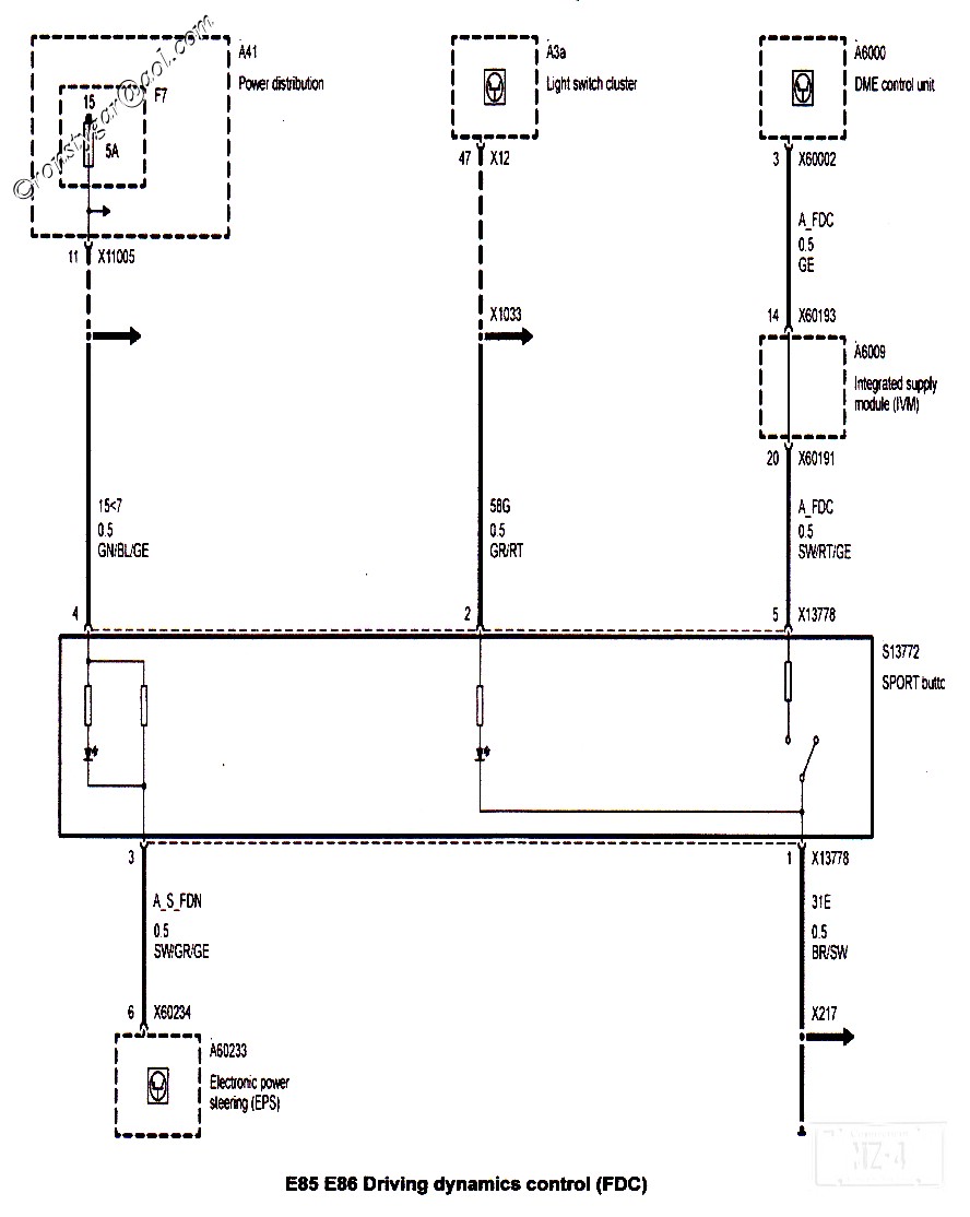
Pin 1 is BR/SW Brown/Black = Ground
Pin 2 is GR/RT Gray/Red = Dimmed lighting
Pin 3 is SW/GR/GE Black/Gray/Yellow = Power steering
Pin 4 is GN/BL/GE Green//Blue/Yellow = Power, fuse 7
Pin 5 is SW/RT/GE Black/Red/Yellow = To DME via module (VM)